10
FN9186.3
January 3, 2006
automatically retries to turn on the MOSFET after a wait
period, during which C
T
is charged and discharged 64 times
and the retry attempt takes place on the 65th time. This wait
period allows the MOSFET junction to cool down.
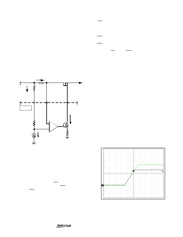
2. Way Overcurrent (WOC) Mode - This mode is designed
to handle very fast, very low impedance shorts on the load
side, which can result in very high di/dt. Typically, the current
limit set for this mode is 300% of the current regulation limit.
This mode uses a very fast comparator, which directly looks
at the voltage drop across R
SNS
and pulls the gate very
quickly to GND (as shown in Figure 14) and immediately
releases it. If the WOC is still present, the IC enters current
regulation mode and the rest of the current regulation
behavior follows as described earlier in undercurrent
regulation mode.
Additionally, as shown in the block diagram, there is also an
OC comparator
, which also looks at the Rsense voltage
drop. When this drop exceeds the Current Limit set point, it
triggers the timeout circuit, which starts ticking and CTx is
allowed to charge. If the current limit condition remains in
effect until after the time-out period expires (CTx voltage
exceeding 1.178V), the gate of the MOSFET is pulled down,
the SSx capacitor is discharged, FLT
is asserted and a new
SS sequence is allowed to begin after ENx
recycle or by
keeping the RTR
/LTCH pin pulled low.
The voltage on OCREF pin is the same as the internal band-
gap reference voltage, which is 1.178V (nominal). A resistor
to GND from this pin sets the reference current (and hence
the reference voltage) for the current limit amplifier and
OC/WOC comparators. The current regulation (CR) duration
is set by the capacitor on CT pin to GND. Once the voltage
on this pin reaches 1.178V, the CR duration expires. Fault
(FLT
) pin goes active (pulls low), signaling the load of a fault
condition and the gate (GT) pin gets pulled low.
Retry vs Latched Fault Operational Modes:
RTR
/LTCH pin dictates the IC behavior after the gate (GT)
pin pulls down following OC timeout expiration. If the
RTR
/LTCH pin is left floating, the gate pin will remain latched
off. It can only be released by de-asserting and reasserting
the enable (EN
) input. If RTR
/LTCH pin is pulled to GND,
then the Retry mode will be activated. In this mode the IC will
automatically attempt to turn-on the MOSFET after a delay,
determined by the capacitor on CT pin. In the Retry mode,
the internal logic charges and discharges the CT cap 64
times during
wait
period. On the 65th time, the FLT output
clears during retry attempt. If the overcurrent condition
persists after the soft-start, the CT pin will again start
charging and the process repeats.
Bias and Charge Pump Voltages:
The BIAS pin feeds the chip bias voltage directly to the first
of the two internal charge pumps, which are cascaded. The
output of the first charge pump, in addition to feeding the
second charge pump, is accessible on the CPVDD pin. The
voltage on the CPVDD pin is approximately 5V. It also
provides power to the POR and band-gap circuitry as shown
in the block diagram. A capacitor connected externally
across CPQ+ and CPQ- pins of the IC is the
flying
cap for
the charge-pump.
The second charge-pump is used exclusively to drive the
gates of the MOSFETs through the 24礎 current sources,
one for each channel. The output of this charge pump is
approximately 10V as shown in the block diagram.
Tracking
Q
Rsns
3K
Rset
-
+
Io
Iset
Vin
Vo
+
-
+
-
ISL6173
25&
WOC
COMPARATOR
GATE
PULLDOWN
CURRENT
FIGURE 14. WOC OPERATION
CH1: V
O
1, CH2: V
O
2, T = 2ms/DIV, C
SS
= 0.066礔
FIGURE 15. TRACKING MODE WAVEFORMS
ISL6173
发布紧急采购,3分钟左右您将得到回复。
相关PDF资料
ISL6174IRZ
IC CIRC BREAKER DUAL LV 28-QFN
ISL61861DCBZ
IC USB PWR CTRLR 3A 8SOIC
ISL6402IR
IC REG TRPL BCK/LINEAR 28-QFN
ISL6413IRZ-TK
IC REG TRPL BCK/LINEAR 24-QFN
ISL6432CB-T
IC REG QD BCK/LINEAR 16-SOIC
ISL6521CBZS2698
IC REG QD BCK/LINEAR 16-SOIC
ISL6528CBZ-TS2698
IC REG DL BCK/LINEAR SYNC 8-SOIC
ISL6529CBZ
IC REG DL BCK/LINEAR SYNC 14SOIC
相关代理商/技术参数
ISL6173EVAL1
功能描述:EVALUATION BOARD FOR ISL6173 RoHS:否 类别:编程器,开发系统 >> 评估演示板和套件 系列:- 标准包装:1 系列:PCI Express® (PCIe) 主要目的:接口,收发器,PCI Express 嵌入式:- 已用 IC / 零件:DS80PCI800 主要属性:- 次要属性:- 已供物品:板
ISL6173EVAL3
制造商:INTERSIL 制造商全称:Intersil Corporation 功能描述:Dual Low Voltage Hot Swap Controller
ISL6174
制造商:INTERSIL 制造商全称:Intersil Corporation 功能描述:Dual Low Voltage Circuit Breaker
ISL6174IRZ
功能描述:IC CIRC BREAKER DUAL LV 28-QFN RoHS:是 类别:集成电路 (IC) >> PMIC - 热交换 系列:- 产品培训模块:Obsolescence Mitigation Program 标准包装:100 系列:- 类型:热插拔开关 应用:通用 内部开关:是 电流限制:可调 电源电压:9 V ~ 13.2 V 工作温度:-40°C ~ 150°C 安装类型:表面贴装 封装/外壳:10-WFDFN 裸露焊盘 供应商设备封装:10-TDFN-EP(3x3) 包装:管件
ISL6174IRZ-T
功能描述:IC CIRC BREAKER DUAL LV 28-QFN RoHS:是 类别:集成电路 (IC) >> PMIC - 热交换 系列:- 产品培训模块:Obsolescence Mitigation Program 标准包装:100 系列:- 类型:热插拔开关 应用:通用 内部开关:是 电流限制:可调 电源电压:9 V ~ 13.2 V 工作温度:-40°C ~ 150°C 安装类型:表面贴装 封装/外壳:10-WFDFN 裸露焊盘 供应商设备封装:10-TDFN-EP(3x3) 包装:管件
ISL617XEVAL1Z
制造商:INTERSIL 制造商全称:Intersil Corporation 功能描述:Dual Low Voltage Circuit Breaker
ISL6185
制造商:INTERSIL 制造商全称:Intersil Corporation 功能描述:Dual USB Port Power Supply Controller
ISL6185_11
制造商:INTERSIL 制造商全称:Intersil Corporation 功能描述:Dual USB Port Power Supply Controller 2.5V to 5V Operating Range